Outback Cooler
(Razorback)
Installation
&
User Manual
DRAFT
12 July 2005
Table of Contents
Outback Cooler Installation Procedure
Adding Desiccant to Front Case Area
Temperature Controlled Settings
Outback Cooler – Installation
The process of installing the Outback Cooler kit is relatively simple and involves no modification of the camera. There are no electrical connections between the Outback Cooler and the Camera.
WARNING: Installing the Outback Cooler to your DSI camera will void the warrantee of the camera. By installing the Outback Cooler you are accepting responsibility for any damage that may occur to the camera.
Equipment
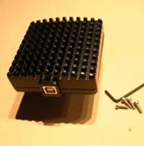
What comes in the Outback Cooler Kit:
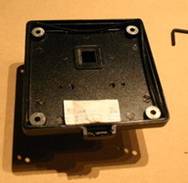
- Outback Cooler replacement back
- Power Cord.
- Allen Key
- White heat conduction paste in plastic bag
What you need to install and use the kit.
- A pair of scissors
- Small flat blade screw driver.
- A tissue might be useful. The white heat conducting compound has a bad habit of getting on everything.
- Silicon if you want to fully seal the case.
- 12V power source capable of delivering 4 Amps
NOTE: You can power up your Outback Cooler before installing it on the DSI camera. See - Powering Your Outback Cooler.
Installation Options
There are two options for installing the Outback Cooler to your DSI. The simple installation procedure described below will get you up and running as simply as possible. The simple option does not address sealing the DSI case and adding desiccant to the forward section of the camera. The DSI case is not sealed as shipped from Meade and sealing requires performing a number of additional steps. See Camera Sealing Description below.
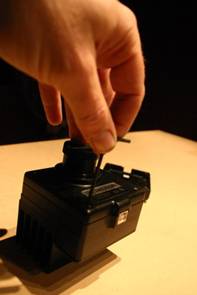
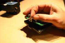
Outback Cooler Installation Procedure
To converting your DSI or DSI Pro camera to Outback cooling follow this step by step procedure.
|
|
|
|
|
|
|
|
|
|
|
|
|
|
|
|
|
|

Adding Desiccant to Front Case Area
Only add desiccant to the front area if you are proficient at working with electronics and assembling cameras. To add desiccant to the front section of the case perform the following steps between step six and seven above:
|
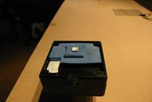
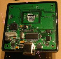
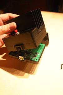
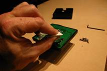
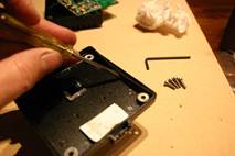
a. Have a good close look at the way the rubber seal goes around the circuit board. You will need to make sure it goes back the same way and it can be a bit difficult. |
|
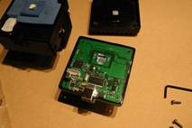
|
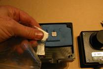
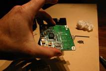
b. Lift the circuit board out using the USB connector. Be careful as the CCD sensor is on the bottom of the board and you don’t want to touch or damage the window. There is a small square rubber seal around the CCD window. This may stick to the CCD and come out with the board or stay in the case. It doesn’t matter which way it goes just make sure it goes back in place. |
|
|
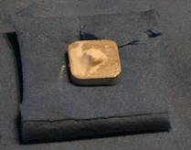
c. Grab the desiccant pack and knead it between your thumb and finger to get it as flat as possible. |
|
|
d. Place the desiccant in the front case just near the USB port entry. The circuit board will rest on the bag and hold it in place. There are no components in the circuit card in this area. |
|
|
e. Ensure the rubber seal is in the correct place. If it isn’t you will need to use the screw driver blade to encourage it to behave. A small smear (very small) may be required to hold it in place. Place the circuit board back into the case. CCD sensor down and USB port in the correct place. |
|
|
f. The circuit board does not sit firmly in the case. Ensure that the desiccant is flat enough for the USB port to seat correctly into its slot. |
|
Camera Sealing Description
Moister in the air inside the camera will condense onto the cold finger and around the CCD. As the camera warms up after the cooler has been turned off the moister will evaporate again. The added insulation reduces the air volume inside the case to help reduce the amount of moisture. A desiccant pack is included in the rear case which will absorb this moisture and reduce condensation. A desiccant bag is also included which can be installed in the front section of the case. So why do you need to seal the case?
In lower humidity areas you could change the desiccant bag in the rear case so that it can continue to pull moister from the air. There are holes in the circuit board near the CCD that air can move between front and rear areas. The period would depend on the average humidly in your area. Maybe once a year or after summer. Leave the desiccant in the plastic bag so it doesn’t absorb any moister before you put it inside.
The desiccant can only absorb a limited amount of moisture. There is enough desiccant to absorb the moister in the case however, if there are any places for air to enter the case more moisture will come along for the ride. Air enters the case as the atmospheric pressure increases and the case pressure equalises. There is no point half sealing the camera as even the smallest hole will let the internal camera pressure equalise.
So what do you need to do to seal the case? Here are a list of areas that need to be sealed:
- Seal around the USB port using silicone sealant. Sealant on both halves of the case so that it is sealed all the way around
- Seal the rear and sides of the USB connector. The USB connect metal has holes on the rear and sides. You really need to cover the USB connector in a thin layer of silicon. You shouldn’t be able to blow through the connector.
- You need to add some silicon under the cap screw heads before you screw the case together
Note: The Outback Cooler rear case is completely sealed to the inside of the camera.
Powering Your Outback Cooler
The Outback Cooler requires a significant amount of power to operate. The Outback comes with a 1.5m power lead with a cigarette lighter plug on the end that contains a 5 Amp fuse. During normal operation the Outback can use up to 4 Amps at 12 Volts. Average current use is around 2.5 Amps. The amount of power used depends on the ambient temperature and level of set temperature. Increasing the fan speed will tend to reduce the power consumption.
The outback can also be powered from a mains 12Volt power supply capable of delivering 4Amps at 12 volts. A 12V battery can be used to power the Outback Cooler. An 18Amp/Hour battery will operate the cooler for between 4 and 6 hours.
If you make up your own lead ensure that there is some form of current limiting device such as a fuse or short circuit protection within the cable or power supply. The polarity of the connector is centre positive.
WARNING: Reversing the power lead polarity will cause damage to the Outback Cooler.
Using the Outback Cooler
Imaging
While the DSI camera is imaging heat is being generated within and around the CCD Sensor. This heat manifest it’s self as noise in the captured image. This noise is know as thermal noise and is relatively systematic for a given CCD sensor. Because the thermal noise is systematic you are able to characterise the noise by capturing “Dark Frame” images taken with the lens capped. When you capture a “Dark Frame” image no light is falling on the CCD, therefore, any counts that accumulate on the sensor must be generated from noise. The majority of this noise consists of thermal noise and is relatively constant from image to image taken at the same CCD temperature. Thermal noise in the image can be reduced by cooling the CCD sensor.
Cooling a typical CCD by around 5 degree’s Celsius can halve the dark current noise generated by the CCD. This is particularly useful for Deep Sky imaging where light levels are very low and exposure times necessarily higher. Imaging with narrow band filters can also benefit from CCD cooling.
The ability of the Outback Cooler to regulate the temperature of the DSI CCD to the same temperature throughout a nights observing eliminated the need to take multiply dark frame sets as the night temperature changes. The Outback Cooler will return the CCD to the same temperature the next time you go out imaging which further reduces the need to take dark frames every session. Dark frames are valid for a given CCD at the same temperature over the same exposure time. So you can reuse your dark frames
Operating Range
 Figure 1- Razorback
Operating Range
Figure 1- Razorback
Operating Range
The Outback Cooler –Razor Back has a fan mounted on the heat sink. The cooler is only able to maintain the set temperature of a band of ambient temperature. The chart at Figure 1 shows the workable operating range for the Razorback cooler version. For a particular set temperature the left hand side of the operating range will use the least current (0-0.5Amps) while the right hand edge will use the most current (3 to 3.5 Amps). To achieve operation on the right hand side of the range higher fan settings will be required. Temperature Controlled fan setting will work across the entire range. With the fan off operation along the far left edge is possible.
Operation
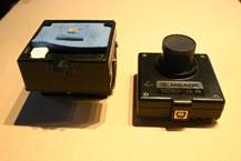
The outback cooler uses a controller circuit to set and regulate the temperature of the DSI CCD image sensor. The CCD temperature is set and indicated on the control panel on the rear of the Outback Cooler (Error! Reference source not found.). The heat sink occupies about 2/3 of the back and the control panel takes up the rest of the space. There is one red button in the middle of the control panel that allows you to change the temperature setting. Each time you press the button, the target temperature moves to the next colder temperature. When you reach the coldest setting it switches back to the warmest.
Seven LED’s that indicate the temperature you have set (the target) and the current temperature of the cold finger. The LED's correspond to temperatures ranging from +20 °C to -10 °C (68 °F to 14 °F) in steps of 5 °C (9 °F), arranged with the warmest temperature at the left, near the button, like this:
Figure 2 - Control Panel
The LEDs can light up as red or green,
green indicating the finger has cooled to that temperature and red meaning it
is either too cold or too hot depending on whether the red LED is at the
warmest end of the lit LEDs or the coldest end. Here is what it looks like if
you turn it on and press the button twice to set the temperature to 10 °C
and the camera is c
urrently warmer than 20 °C:
Figure 3 - Set Temperature 10C - CCD > 20C
This means the target temperature is
10 °C and the finger is currently at least 20 °C. As the finger cools
down, the LEDs will turn from red to green – it takes a minute or two to cool
the chip down to the target temperature. With the finger between 10 and
15 °C the dis
play looks like this:
Figure 4 - Set Temperature 10C & CCD at 15C
When the t
arget temperature is reached you get the display at Figure 5
Figure 5 - Set Temperature 10C and CCD regulated at 10C
If you set a hotter preset temperature than the current CCD temperature or the control circuit can overshoot the desired temperature briefly. In this case a red LED will again appear, but this time with a green LED at the cold end of the display indicating that the temperature is colder than the target you have set. If it cools down to below 5 °C with the target set at 10 °C, you will see:
Figure 6 - Set temperature Figure 2 10C and CCD warming from 5C
In all cases, the temperature of the finger is indicated by the green LED at the coldest temperature, and the target is indicated by the red LED at the coldest temperature (unless the actual temperature is just colder than the target, in which case there are only green LEDs).
Once the temperature has stabilised at the target you will see the LED at the target temperature slowly switching between red and green as the temperature changes slightly around the target. The temperature will stay within 1 °C of the target in this condition.
Powering Down
During operation the heat sink becomes very warm. When the power is removed this heat will begin to migrate forward onto the CCD. This build up of heat will cause thermal stress on the chip. By allowing the cooler to operate at the lowest temperature set point (20C) and a high fan setting (FAN4) for 10 minutes before removing power you will reduce the thermal stress placed on the CCD chip.
Fan Control Mode
The fan speed of the Razor back model is controlled by the controller via the button and LEDs. To enter fan control mode hold the button down for one second until the LEDs start to flash red. The number of LEDs flashing indicates the current fan mode, and pressing the button steps through the modes just as with the temperature settings. The unit remains in fan mode for about five seconds after the last button press. You can also change back to temperature control mode by holding the button down for one second again.
There are 7 fan modes:
1. Off
2. Fixed speed low
3. Fixed speed medium
4. Fixed speed high
5. Temperature controlled, gentle
6. Temperature controlled, moderate
7. Temperature controlled, aggressive
![]()
Fixed
Speed Settings
In the fixed speed
settings the fan will maintain aconstant speed. Higher fan settings reduce the
power used by the Outback Cooler to
maintain a given set temperature.
Temperature Controlled Settings
In the temperature controlled modes the fan speed is adjusted to limit the temperature rise of the heat sink above the target temperature of the cold finger. For the gentle mode, the heat sink temperature is allowed to rise to 40 °C above the cold finger. The moderate mode allows 30 °C rise and the aggressive mode allows 20 °C. In these modes, the fan speed responds to both the temperature of the heat sink and the target temperature you have set for the cold finger, so it will change when you change the temperature setting. The fan stays off until the heat sink warms to near the specified temperature above the target temperature then increases in speed as the heat sink warms further.
Built In Test Functions
The Outback Cooler continuously monitors correct operation and reports any faults via the 7 LEDs on the control panel. When an error is detected, cooling operations cease and the error is reported by flashing one of the red LEDs. The errors and the corresponding LED are:
1. Cold finger sensor malfunction - reset power to attempt to clear error. If fault does not clear or re-occurs contact your supplier.
2. Heatsink sensor malfunctions, or overheats (above 100 °C). – Remove power. If heatsink is very hot allow to cool with power removed. Restart cooler and select a higher set temperature. If fault re-occurs while heat sink is cool contact your supplier.
3. Fan failure – Check that nothing is obstructing the fan from rotating. If you blow into the fan the fan should spin. If fan turns freely and is unobstructed contact your supplier.
4.
Low voltage (below about 6 V). If
powered via a 12V battery check the batter charge level. If using a mains power
supply check the supply if functioning correctl
y.
![]()
Notes:
1. There is a debugging mode that reports information about internal control variables, which is activated by holding down the button when power is applied. In this mode the 5th and 7th LED's (0 and -10 °C) do not operate as normal and the -10 °C LED continuously flashes red and green. If you accidentally activate this mode, remove the power and reconnect without holding the button down.
- The LEDs may flicker slightly during operation – This occurs near internal temperature boundaries and power fluctuations as the control regulates the amount of cooling to the CCD.
Specifications
|
Parameter |
Description |
|
Voltage |
8 to 13.8 V |
|
Current |
4A (maximum) |
|
Cooling Range |
+20 to -10 Deg Celsius Regulated in 5 Deg C steps |
|
Fan Speed Control Modes |
Off, Fixed, Temperature Control |
|
Power Cable |
5AMP Fuse Centre Positive Connector |
|
Desiccant |
0.5gram bag |
Disclaimer
The supply of the Outback Cooler warrants the Outback Cooler for faults occurring when installed and operated in accordance with this manual for a period of 12 months from the date of purchase. The supplier undertakes no responsibility for the Camera that the Outback Cooler is installed to, or any faults that may occur with the camera during installation or operation.